Uml Class Diagram Association Cardinality
Introduction to Class Diagram
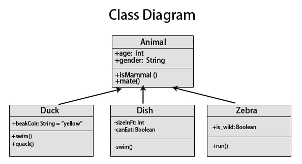
The class diagram is one of the types of UML diagrams which is used to represent the static diagram by mapping the structure of the systems using classes, attributes, relations, and operations between the various objects. A class diagram has various classes; each has three-part; the first partition contains a Class name which is the name of the class or entity which is participated in the activity, the Second partition contains class attributes that show the various properties of the class, the third partition contains class operations which shows various operations performed by the class, relationships shows the relation between two classes.
Relationships
In a class diagram, it is necessary that there exists a relationship between the classes. Unfortunately, the similarity of various relationships often makes it difficult to understand them. Below are the relationships which exist in a class diagram.
1. Association
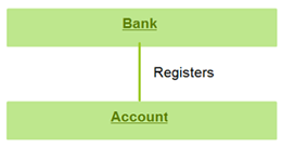
Between two other classes in an association relationship, an association class forms a part of it. Additional information about the relationship could be obtained by attaching the association relationship with the association class. Various operations, attributes, etc., are present in the association class.
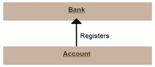
The below diagram shows an association between bank and account.
2. Multiplicity
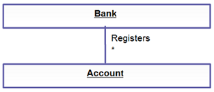
The number of elements or cardinality could be defined by multiplicity. It is one of the most misunderstood relationships which describes the number of instances allowed for a particular element by providing an inclusive non-negative integers interval. It has both lower and upper bound. For example, a bank would have many accounts registered to it. Thus near the account class, a star sign is present.
3. Directed Association
This is a one-directional relationship in a class diagram that ensures the flow of control from one to another classifier. The navigability is specified by one of the association ends. The relationship between two classifiers could be described by naming any association. An arrow indicates the direction of navigation.
The below example shows an arrowhead relationship between the container and the contained.
4. Reflexive Association
The association of a class to itself is known as Reflexive association, which could be divided into Symmetric and Asymmetric type associations. In Symmetric reflexive association, the semantics of each association end has no logical difference, whereas, in Asymmetric Reflexive Association, the associated class is the same, but there is a semantic difference between the ends of the association.

5. Aggregation
In this type of relationship, a more complex object is created by assembling different objects together. The interaction within the different groups of objects is defined by Aggregation. The integrity of the objects is protected, and the response of the assembled objects is decided by the control object. In aggregation, the classes nurture the 'has a relationship.
![]()
6. Composition
It is a form of aggregation which represents the whole-part relationship. Here, the part classifier lifetime is dependent on the whole classifier lifetime. In a class, a strong life-cycle is represented by the composition relationship. There is usually a one-direction flow of data here. It is generally indicated by a solid line.
![]()
7. Generalization
In this kind of relationship, the child model is based on the parent model. The relationship is used to describe various use-case diagrams and ensures that the child class receives the properties present in the parent. The child model could reuse the attributes of the parent model with the help of the generalization relationship. Hence the distinct attributes need to be defined only in the child; the rest it would inherit from the parent. There could be single parents, multiple children, or multiple parents, single child characteristics in this relationship. There are no names in the generalization relationships. It is also known as the 'is a relationship.

8. Realization
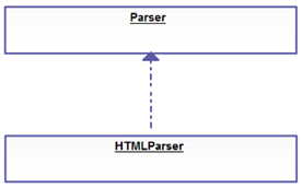
The behavior of one model element is realized by the specified behavior of another model element. This type of relationship doesn't have any names.
Why should we use the Class Diagram?
The structure of a system is defined by a Class Diagram by showing its attributes, relationships among objects, and so on. It is the backbone of object-oriented modeling and could also be used for Data modeling. Class Diagrams help in making pre-plans which eases the programming process. Moreover, you could always make changes to the Class Diagram as it's kind of annoying to code different functionality after facts. It is a design plan based on which a system is built. It is easy to understand without much technical knowledge required.
Class Diagram provides a static view of the application, and its mapping ability with object-oriented language makes it ready to be used in construction. Unlike the sequence diagram, activity diagram, etc., the class diagram is the most popular UML diagram. Below is the purpose of a Class diagram.
- The static view of an application is designed and analyzed.
- A system's responsibilities are described by it.
- The components and the deployment diagram's base is the class diagram.
- The forward and reverse engineering is influenced by the Class Diagram.
Types of Class Diagram
Class Diagram could be divided into three components –
The Upper Section consists of the class name and is a mandatory component. The middle section described the class qualities and used them while describing a class's specific instance. The bottom section describes class interaction with the data.
Moreover, a UML is divided into Behavioural and Structural Diagram with Class Diagram falling under the Structural diagram.
Advantages of Class Diagram
A class diagram could be implemented in different phases of a project and is the heart of the UML. A representation of reality is created by the class diagram by appearing on the domain model during analysis. The software modeling is done during the design phase, whereas the code is generated during the implementation phase. The foundation of software products is the class diagrams which are an essential part of any project.
A sense of orientation is given by the class diagrams. The structure of the system is analyzed in detail by the class diagram, and also the synergy among different elements is overviewed by them along with their properties. It is fast and easy to read and could be created easily if the right software is in place. Any system that needs to be created, the class diagrams form the foundation for that.
Benefits
- Any simple or complex data model could be illustrated using the class diagram to gain maximum information.
- The schematics of an application could be understood with the help of it.
- Any system need could be visualized and passed across the business for specific action to be taken.
- Any requirement to implement a specific code could be highlighted through charts and programmed to the described structure.
- A description that is implementation-independent could be provided and passed on to the components.
Disadvantages of Class Diagram
Though Class Diagram is the first thing to consider in a production environment to build a flawless system, it certainly has its fair share of cons as well.
- The class diagrams might often take a longer time to manage, and maintain which is sometimes annoying for a developer. It requires time for the synchronization with the software code to set it up and maintain. Often developers or small companies find it difficult to synchronize the code as it required an added amount of work.
- A lack of clarity in understanding the beneficiary of the diagram is also a disadvantage. As software developers work with code, sometimes the class diagrams are not that helped much. However, project managers could be benefited from the diagrams as it gives an overview of the workflow of a particular tool. Hence, there is often an argument to not waste time on the class diagrams and focus rather on using a whiteboard or paper to draw the diagram.
- An overcomplicated or overwhelming diagram doesn't help software developers in their work. There could be situations when the developers are frustrated due to the structure of the class diagrams. Mapping out every single scenario could make the diagram messy and hard to work with. Using high-level information could somehow help to combat such issues.
- Putting overemphasis on the design could cause a hindrance to the developers and companies. The stakeholders could easily overanalyze the problems after looking into the class diagram, and putting too much effort into the features of software might lead to a loss of focus. People need to get down on the actual work rather than spending time looking into the diagram and solving issues.
As you can see, despite the importance of the Class Diagram in the software development life cycle, it is certainly not without any shortcomings and could make life difficult for the developers and companies if not used wisely.
Example of Class Diagram
Without the fuss of technical constraints, a diagram is fairly easy to create. To use an ATM, it is only required for a customer to press a few buttons to get their cash. Despite the ease with which the cash flows out, the backend system has multiple layers of security which needed to be passed to prevention in fraud, money laundering, and so on.
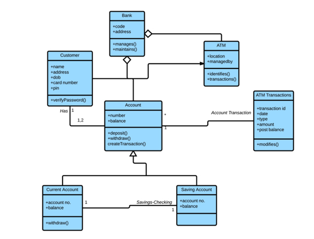
As seen over here, there are several entities that follow the properties of different relationships as described earlier. These relationships describe the structure in which an ATM system is built and the layers of security it has to pass through to ensure transparency and integrity in the transaction.
There are three perspectives in which the class diagram could be divided –
- First is the conceptual perspective which the real-world objects are described with the help of conceptual diagrams. The domain under study is represented by the diagram. It is independent of language and is class-related.
- The software components are described by the Specification perspective with interfaces and specifications. In the case of the specific implementation, however, no commitment is given.
- A specific language implementation could be done with the Implementation perspective class diagrams.
Working with Class Diagram
For software development, the most important UML diagram is the Class Diagram. To draw a class diagram representing various aspects of an application, a few of the properties which needs to be considered are –
- A meaningful name should be given to a class diagram describing a system's real aspect.
- It is necessary that in advance, one understands the relationship between each element.
- To develop a better product, the responsibility among the classes needs to be recognized.
- To avoid making the diagram complicated, the specific properties of a class should be specified.
- Documentation is a good practice in any software development project. Thus defining any aspect in a diagram needs proper documentation or notes for others to comprehend. A software development team at the end should understand what has been configured in the diagram.
- Drawing on a whiteboard or plain paper is needed before the creation of the final version. However, one needs to ensure that only the diagram that is ready should be submitted, which might include several reworks.
How will this technology help you in career growth?
If you are in the software industry, it is imperative that you need to define the structure of your problem beforehand to build a good product. A class diagram helps in understanding the different aspects of a project lifecycle and helps in understanding the relationship within the elements in the code.
Conclusion
To design and visualize the software system artifacts, the standard language used is the UML. The relationship between the different objects is described by the class diagram, which ensures the design and analysis of an application and views it in its static form. Being the most important UML diagram, the class diagram consists of class, attributes, and relationships, which are its essential elements. To get an idea of the application structure, the class diagram is used, which helps in reducing the maintenance time.
Recommended Articles
This article has been a guide to What is a class diagram. Here we discuss the basic concepts with relationships and different type of class diagram. You can also go through our other suggested articles to learn more –
- What is Data Analyst?
- What is SQL Server?
- What is a Hive?
- What is Apache Spark?
Source: https://www.educba.com/class-diagram/
Posted by: zuniegasharlenenoes.blogspot.com
Posting Komentar untuk "Uml Class Diagram Association Cardinality"